Step 7: analog signal normalization
Update: See https://github.com/planken/Step7/blob/ma... for the latest source code.
You can use the Siemens function FC105 SCALE to scale an analog signal to engineering units but mostly this doesn't work well for me. One problem is that FC105 assumes that the A/D value lower limit is either 0 (uni-polar) or -27648 (bi-polar) and the upper limit 27648. However, this is often not the case. There may be a modest baseline noise at the low end and the maximum input may not exactly be 27648. And if you have a 0-20mA input using a 4-20mA device, you would need to manually correct the A/D input to FC105 or manipulate the lower and upper engineering limits.
Years ago I decided to roll my own. (Then last year I found that a similar function was available on the Siemens website, but not quite the same.)
I am still using the same math, with a few changes. It allows for quick commissioning by entering two coordinates for a low and a high A/D value, with their corresponding engineering values.
Suppose we have a motor with a 4-20mA CT connected to a 0-20mA analog input and we want to scale the A/D value to amps for display on an HMI.
First, we will establish the first coordinate pair 0: with the motor not running, record the A/D value and use a lower limit for the engineering units of 0.0A. In this example, we are receiving an A/D value of 5538 (just over 4mA). So use:
AD_0 = 5538
Scale_0 = 0.0
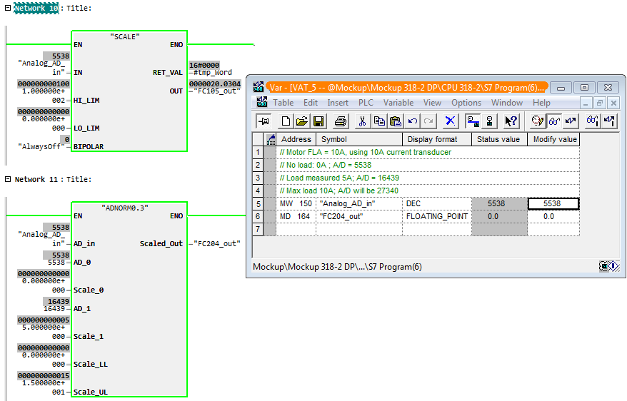
Top: Siemens FC105, bottom: custom FC. Motor without load.
Then we will establish the upper coordinate pair 1: with the motor running, measure the motor load in amps and record the A/D value. E.g. we measure 5A at A/D = 16439. So use:
AD_1 = 16439
Scale_1 = 5.0

Top: Siemens FC105, bottom: custom FC. Motor at 50% of FLA.
The function will extrapolate, so if the motor load exceeds the value for the upper value pair it will be reflected in the function's output signal. For example, at full load amps of 10A the FC output will be 10.

Top: Siemens FC105, bottom: custom FC. Motor at 100%.
Since I am using input type ANY, Step 7 is unable to show the value online, so we use a VAT instead for visualization. This FC will allow for quick commissioning and requires no adjustments for loads that exceed the measured value, as the FC extrapolates.
I attached a small Step 7 library file to this post.
ADNORM interface description
AD_in: A/D value from the card as INT.
AD_0 and Scale_0 The values on the lower side of the graph. Enter the A/D value (INT) with the corresponding output value (REAL).
AD_1 and Scale_1 The value pair on the upper side of the graph. Enter the A/D value (INT) with its corresponding output value (REAL).
Scale_LL and Scale_UL are the values to which the engineering units will be clipped if exceeded. Keep in mind that the output value can be extrapolated. (REAL)
Scaled_out: the scaled output value as either INT, DINT, or REAL.
The function's math
The calculation is straight forward. We calculate the A/D span and scale the input to that. Then we scale that against the output span.
Scaled_Out = (( AD_in - AD_0) / (AD_1 - AD_0)) * (Scale_1 - Scale_0) + Scale_0
Then we apply the limits Scale_LL and Scale_UL to ensure the output always lies within that range.
Caveat when using global memory (M)
One very important thing to consider is this. When using a global address (M) for the output, the variable type must be properly assigned in the symbol table. Failure to do this will fail the type detection of the ANY pointer and may result in unpredictable or unexpected results. So when intending to use a REAL output, the MD address must be defined in the symbol table as REAL.
Parameter of type ANY
For more details, see Step 7: ANY pointer parameter.
| Attachment | Size |
|---|---|
| 24.48 KB |
Comments
Thanks for this!
You’re welcome.